Servos
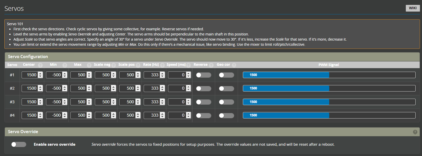
Open the Servos tab and confirm that you have the correct number of servos. If this is not the case, please confirm you have installed the correct firmware (either 'M' motorised or servo tail) or if you are using a drone FC that your Remapping is correct.

Servo Numbering
Direct
Servo 1 - Pitch
Servo 2 - Roll
Servo 3 - Collective
Servo 4 - Rudder
CCPM
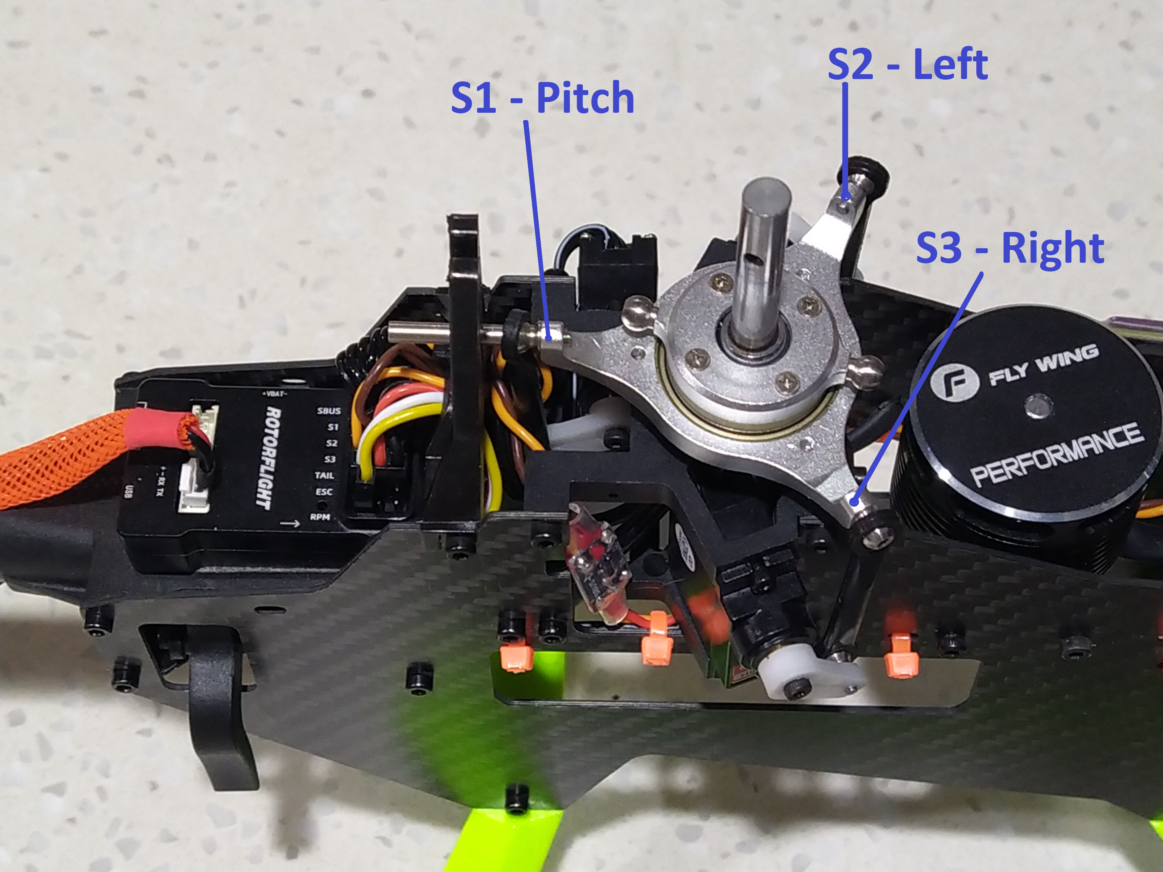
For 120, 134 and 140 deg CCPM swashplates. Looking from the tail towards the nose of the helicopter:
Servo 1 - Pitch (inline with the centerline of the helicopter)
Servo 2 - Left side
Servo 3 - Right side
Servo 4 - Rudder

Fixed pitch
90deg L
Servo 1 - Pitch (inline with the centerline of the helicopter)
Servo 2 - Side servo
Servo 3 - Rudder
Picture to go here
90deg V
Servo 1 - Left side
Servo 2 - Right side
Servo 3 - Rudder
Picture to go here
Servo Override
The toggle at the botom of this page enables the servo overrides. The purpose of this is so that each servo can be driven by the slider to calibrate the range and center points. Beside each servo is an individual override.
The servo override slider scale is in degrees

Servo Configuration parameters

Center
In general this will be 1500us for cyclic servos and 760us
Min and Max
These are hard limits to prevent servos binding or moving outside of their mechanical limits. If a servo is commanded to a point that is greater or less than it is capable it will buzz and likley burn out. These settings should be used to limit the command.
Scale Neg and Scale Pos
Scales the negative and positive direction of the servo to match the commanded angle.
Rate
This is the servo frequency. This will be specified by the manufacturer. A large proportion of servos suitable for cyclic operate at 333Hz.
For Rotorflight 2 it is recomended that tail servos are assigned to a different timer than cyclic servos (see Remapping). This means that tail servos can be set to a different frequency (i.e. faster)
Speed
This is used to slow down servos for use on retracts etc. Additional servos currently have to be configured using CLI commands.
For Cyclic and tail servos this should only be set to 0.
Reverse
Toggle for forward or reverse servo direction
Geo Cor
Geometry Correction. Servos are rotary, so at high angles this results in smaller swashplate movement for each degree of servo movement. Geometry correction accounts for this and provides better control at high angles (e.g. 3D flight).
In order to use this feature it is important to set the servo arm at 90deg (with servo center) and calibrating the servo scale.
Servo Setup and Calibration
Step 1
Confirm and set the servo rate as specified by your manufacturer. For many digital servos this is 333Hz.
Step 2
- Set each of the override sliders to 0 degrees
- Set center to your servo manufacturers recomendation. For Cyclics this will be 1500 or 1520us.
- Fit servo arms to as close to 90 degrees as possible.
Step 3
- Set Servo override to on
- Slide Servo 1 override in the positive direction (i.e. right)
- confirm the servo arm travels up towards the swashplate. If not toggle the servo reverse.
Repeat with remaining cyclic servos.
Step 4
- Slide the servo override back to 0 degrees.
- Slowly increase or decrease the center until the servo arm is at 90 degrees
Step 5
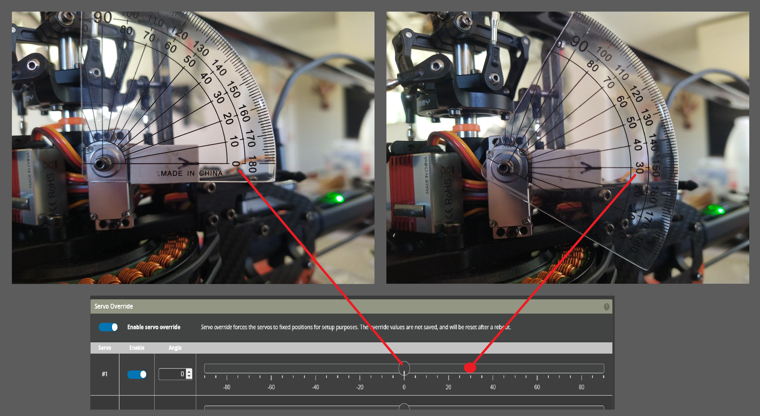
Calibrate the range. Not all servos move by the same angle for each change in command. This step calibrates this range so that the servo's move by the same amount. This means that the Geometric Correction can be used.
- Set the override to a positive value (e.g. 30deg)
- measure the current servo arm angle and increase or decrease the Scale Pos until the servo arm angle matches the override angle.
